Monday, September 22, 2014

Circuits WS & Lab


I won't make you turn this in this year (I want you to concentrate on your project proposals) but you should know how to do this (it might show up on the midterm). 


Just stick with measuring R and V for now, calculate the current (this way we don't have to worry about blowing fuses).


Circuits Lab

The purpose of this lab is to theoretically estimate and empirically measure current and voltage for a series circuit and a parallel circuit.  Your group has the following materials to complete the lab: breadboard, resistors, 9V battery and leads, multimeter, and jumper wires.

Lab Procedure
1.       Begin by measuring the voltage of your 9V battery.  Place the red lead on the “+” side of the battery and the black lead on the “–“ side of the battery and note the measurement as VDC.

2.       Identify the resistance values of the resistors you’ve been given by using the Resistor tables.  On your lab, note the value of the resistor you used for R1, R2, and R3. 


3.       Measure the voltage drop across each resistor.  V1 corresponds to the voltage drop across R1, and so on.  Record the voltages for both the series and parallel circuits as the experimental values.
4.       Calculate the current.  In the series circuit, you will only have to calculate I.  In the parallel circuit, you will need to calculate I1, I2, and I3.  Record the currents for both the series and parallel circuits as the experimental values.
5.       Using the values you obtained for VDC, R1, R2, and R3, calculate the theoretical values for the voltages.
6.      
Calculate the percent error for the voltages and currents.  Percent error is calculated as:


Where theoretical are values using V = 9V, and ideal resistor values, and experimental are using actual voltage and resistor values you measure with your multimeter.

Resistor Color Codes – Brown resistors
1st and 2nd color bands (representing first two digits of resistance)
Black = 0                 Orange = 3              Blue = 6                   Gray = 8
Brown = 1               Yellow = 4               Violet = 7                                White = 9
Red = 2                    Green = 5
3rd color band (multiplier)
Black x 1                  Orange x 1k                             Blue x 1 meg          
Brown x 10              Yellow x 10k                            Silver ÷ 100
Red x 100                                Green x 100k                           Gold ÷ 10
4th color band (tolerance)
Gold = 5%                               Silver = 10%                            None = 20%           

Blue (precision) Resistor
: 1st 3 bands = 1st three num’s of R, 4th band is multiplier, 5th is tolerance.
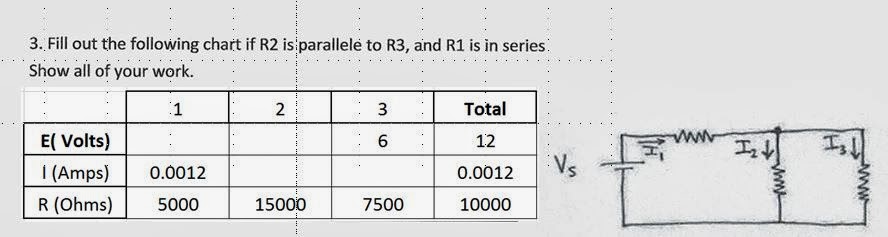
#1~~~~~~~~~~~~~~~~~~~~~~~~~~~~~~~~~~~~~~~~~~~~~~~~~~~~~~~~~~~~~~~~~~~~~:


#2~~~~~~~~~~~~~~~~~~~~~~~~~~~~~~~~~~~~~~~~~~~~~~~~~~~~~~~

Bring up excel, and create some spreadsheets with the tables shown below. 


#3~~~~~~~~~~~~~~~~~~~~~~~~~~~~~~~~~~~~~~~~~~~~~~~~~~


Make sure you understand how to add resistors in parallel and in series for the test.


If you finish, play around making some of the other ciruits from the electronics kit!  Google what you are making to see how it works! 


Electricity!

Electricity!


Static Electricity: Two surfaces, one with high resistance (insulator).  Materials with weakly bound electrons tend to lose them while materials with sparsely filled outer shells tend to gain them. -  Triboelectric effect.


Leyden Jar:
A Leyden jar, or Leiden jar, is a device that "stores" static electricity between two electrodes on the inside and outside of a glass jar. It was the original form of a capacitor (originally known as a "condenser").


It was invented independently by German cleric Ewald Georg von Kleist on 11 October 1745 and by Dutch scientist Pieter van Musschenbroek of Leiden (Leyden) in 1745–1746.[1] The invention was named for the city.

The Leyden jar was used to conduct many early experiments in electricity, and its discovery was of fundamental importance in the study of electricity.


Lightning: Created from electrically charged regions within  clouds, no one really understands how these charges build up.


Lightning rod experiments

In 1752, Franklin proposed an experiment with conductive rods to attract lightning to a Leyden jar, an early form of capacitor.

Such an experiment was carried out in May 1752 at Marly-la-Ville in northern France by Thomas-François Dalibard. An attempt to replicate the experiment killed Georg Wilhelm Richmann in Saint Petersburg in August 1753, thought to be the victim of ball lightning. Franklin himself conducted the experiment in June 1752, supposedly on the top of the spire on Christ Church in Philadelphia.


Electrical Current: Electrons moving in a wire, or ions in an electrolyte.


Ampere (A), Amp, unit of electric current.  It's the amount of electric charge passing through a conductor.


Ohm's Law:

http://phet.colorado.edu/sims/ohms-law/ohms-law_en.html


Induction:


Induction motor:


Electromagnetism:

Electromagnetism, or the electromagnetic force is one of the four fundamental interactions in nature, (the other three being the strong interaction, the weak interaction, and gravitation.) 
 

Originally electricity and magnetism were thought of as two separate forces. This view changed, however, with the publication of James Clerk Maxwell's 1873 Treatise on Electricity and Magnetism in which the interactions of positive and negative charges were shown to be regulated by one force.

.
There are four main effects resulting from these interactions, all of which have been clearly demonstrated by experiments:


 1.   Electric charges attract or repel one another with a force inversely proportional to the square of the distance between them: unlike charges attract, like ones repel.


2.    Magnetic poles (or states of polarization at individual points) attract or repel one another in a similar way and always come in pairs: every north pole is yoked to a south pole.


3.    An electric current in a wire creates a circular magnetic field around the wire, its direction (clockwise or counter-clockwise) depending on the direction of the current.

4.    A current is induced in a loop of wire when it is moved towards or away from a magnetic field, or a magnet is moved towards or away from it, the direction of current depending on that of the movement.


Electromagnet:
The electricity flowing through the wire arranges the molecules in the nail so that the nail becomes magnetic.  When the current is gone, the nail is no longer magnetic.


Telegraph:


Electric Generator:


Device that converts mechanical energy to electrical energy (by pushing a magnet past a wire). The source of mechanical energy may be a reciprocating or turbine steam engine, water falling through a turbine or waterwheel, an internal combustion engine, a wind turbine, a hand crank, compressed air, or any other source of mechanical energy. Generators provide nearly all of the power for electric power grids.


Nikola Tesla; 10 July 1856 – 7 January 1943, invented AC induction motor.


Thomas Edison, Feb 11, 1847 - Oct 18, 1931 - "The Wizard of Menlo Park"


Breadboards:


Using a multimeter:


Resistor Color Code: